33+ directional coupler block diagram
What this means is that the power out of. Power divider based on vertical elliptical directional couplers with increased isolation and bandwidth In this.
2
Typically the coupling coefficients for a directional coupler are in the range of approximately.
. Insertion loss varies from 09. C1 and C2 have 500-V. D1 and D2 are germanium diodes 1N34 or equiv.
An electrical connector is an electro-mechanical device used to join electrical terminations and create an electrical circuit. Download scientific diagram 3 dB directional coupler structure from publication. Data Drawings Downloads DATASHEET View Data View Graphs.
Electrical connectors consist of plugs male-ended and jacks. Up to 40 GHz. 025 c200001 As a result we find that 1 c21.
BDCH-25-33 25 dB SMT Bi-Directional Coupler 800 - 3000 MHz 50Ω Generic photo used for illustration purposes only. Catalog and custom designs available. The bridge-based coupler covers a frequency range of from 9 kHz to 7 GHz with a power rating of 33 dBm 2 watts for a 50 ohm Ω matched load.
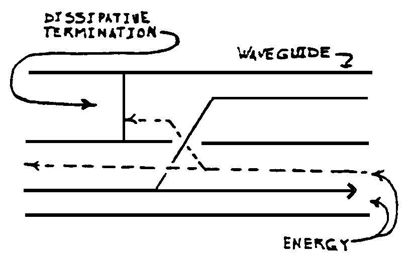
The power measurements include incident power reflected power. A Internally the model of the directional coupler consists of 4 waveguide segments which capture the propagation and a zero-length. A Directional coupler is a device that samples a small amount of Microwave power for measurement purposes.
Directional coupler circuit block. Fig 1946Schematic diagram of the high-power directional coupler. R1 and R2 are 47- or 51-Ω 12-W resistors.
A directional coupler is a four-port circuit where one of the port is secluded from the port that serves as the input and directional couplers are also passive reciprocal networks. Ad High Frequency Single and Dual Directional Couplers to 40 GHz in Stock Now.
2
2

Product Catalog

Product Map For Rf Components And Modules Connectivity Tech Notes Rf Components And Modules Tdk Product C Base Transceiver Station Inductors Connection
2
2

Product Map For Rf Components And Modules Connectivity Tech Notes Rf Components And Modules Tdk Product C Base Transceiver Station Inductors Connection
2

Application Of Accelerators And Storage Rings Springerlink
2
2

These Symbols Indicate Controls And Mechanical Coupling Links Actions Connections Static Or Dynamic Devices Floor Plan Symbols Electrical Symbols Mechanic
2

Class Definition For Class 333 Wave Transmission Lines And Networks

Controls Instruments For The Me 262a War Thunder Messerschmitt Messerschmitt Me 262
2

Class Definition For Class 137 Fluid Handling